


All Categories
- Industrial LCD display
-
Industrial Products
- DC Servo Drive
- AC Servo Drive
- other
- Heidelberg
- FANUC
- IFM
- Meter
- CCD
- Membrane Keypad
- Film
- YOKOGAWA Module
- Card
- ABB
- MITSUBISHI
- FANUC
- KEYENCE
- BECKHOFF
- Honeywell
- HOLLYSYS
- FUJI servo drives
- HP
- solenoid valve
- thermostat
- Siemens adapter
- color oscilloscope
- Fujitsu connector
- CHELIC
- SMC
- CISCO Module
- INTEL
- Key board
- FAIRCHILD
- Motherboard
- Board
- Bearing
- other
- Control Panel
- Contactor
- Circuit
- OMRON
- Relay
- Controller
- Photoelectric Switch
- Photoelectric Sensor
- Original
- Fan
- Motor Driver
- Limit Switch
- Amplifier
- power supply
- LENZE
- Cable
- Encoder
- Sensor
- Transformer
- Fiber Optic Sensor
- Protection Relay
- Temperature Controller
- Proximity Switch
- Switch Sensor
- Siemens
- Industrial board
- HMI Touch Glass
-
HMI Full Machine Whole unit
- OMRON HMI Touch Panel
- Siemens HMI Touch Panel
- Mitsubishi HMI Touch Panel
- Allen-Bradley automation HMI Touch Panel
- DELTA HMI Touch Panel
- KINCO DELTA HMI Touch Panel
- HITECH HMI Touch Panel
- WEINTECK HMI Touch Panel
- WEINVIEW HMI Touch Panel
- PRO-FACE HMI Touch Panel
- SIMATIC HMI Touch Panel
- PANASONIC HMI Touch Panel
- KEYENCE HMI Touch Panel
- WEINVIEW HMI Touch Panel
- HITECH HMI Touch Panel
- FUJI HMI Touch Panel
- SCHNEIDER HMI Touch Panel
- other
- Module
- lcd inverter
- Membrane Keypad Switch
- Winni Touch Screens
- Frequency Inverter
- Servo Motor
- PLC
Recommended Products
Home » News
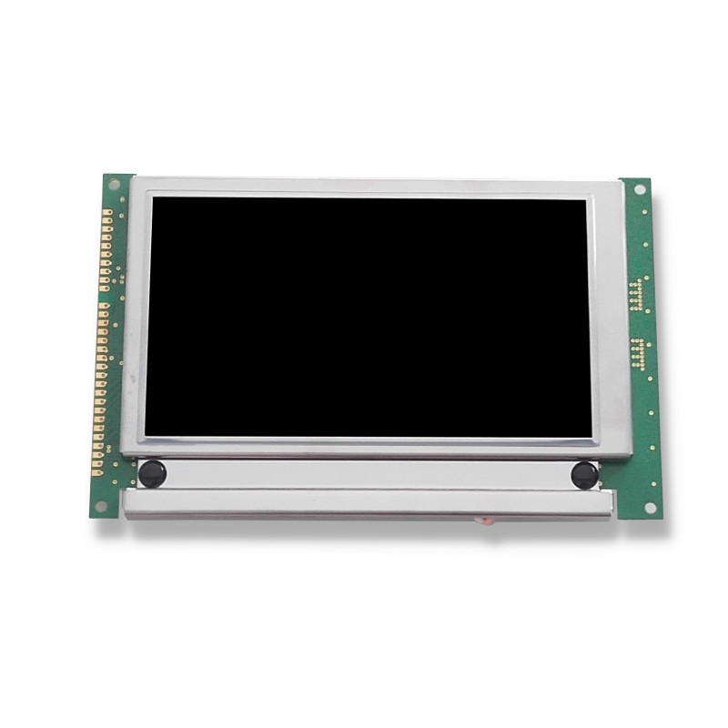
In a simple way, we can divide TFT LCD into three parts, from bottom to top they are: light system, circuit system and light and color control system.In manufacturing process, we’ll start from inner light and color control system and then stretch out to whole module.

It’s accustomed to divide TFT LCD manufacturing process into three main part: array, cell and module. The former two steps are about the production of light and color control system, which contains TFT, CF (color filter) and LC (liquid crystal), named a cell. And the last step is the assembly of cell, circuit and light system.
TFT LCD Manufacturing flow chart
1. Array
In order to enhance productivity, in this step we’ll do a series of procedure on a large glass, which will be cut into smaller pieces in the following step.
First, let me introduce a crucial material, ITO, to you. ITO, abbreviation of Indium tin oxide, has the characteristic of electrical conductivity and optical transparency, as well as can be easily deposited as a thin film. Thus it’s widely used to create circuit on glass.
Now let’s turn to the production of TFT and CF. Here is a common method called PR (photoresist) method. The whole process of PR method will be demonstrated in TFT production.
TFT:
◇ Deposit semiconductor material and ITO in designed order on glass substrate.
◇ Photoresist coating.
◇ Partial exposure, then clean the exposed photoresist.
◇ Tear off the semiconductor and ITO without the cover of photoresist to form part of the circuit.
◇ Clean the remain photoresist.
◇ To build the whole circuit, we often need to repeat the steps for 5 times.
CF:
◇ Create a black matrix on the glass substrate as the boundary using PR method.
◇ Coat red, green and blue material within black matrix separately using PR method.
◇ Coat a overcover on RGB (red, green and blue) layer.
◇ Deposit ITO circuit.
2. Cell
In this step we’re going to assemble the TFT and CF glass and fill in LC at the same time.
◇ Coat polyimide film, using to constrain the initial direction of LC molecule, on the ITO side of both TFT and CF glass.
◇ Use glue to build a boundary for LC on both glass. And on CF glass, apply one more layer of conductive adhesive. This enable LC molecule link to the control circuit.
◇ Fill LC within the boundary.
◇ Stick two glass together, then cut the large glass into small pieces in line with standard.
◇ Attach polarizer film on the both side of the incised glass.
3. Module
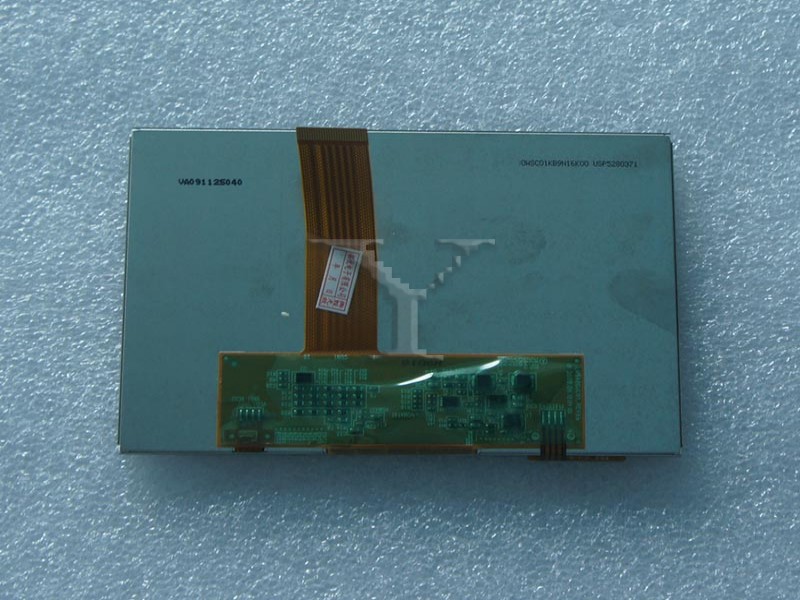
First link the cell to circuit system.
◇ Link the cell to driver IC.
◇ Link driver IC to FPC (flexible printed circuit).
◇ Link FPC to outer PCBA (printed circuit board assembly).
Next prepare the light system
◇ Attach the light source, usually LED or CCFL, on light guide plate, under which there is reflector film
◇ Put the diffuser film and prism film on light source in turn. Together with reflector film, these two films are used to turn the point light from light source into area light and enhance light intensity.
◇ Link the light source to light control circuit, always another type of PCBA.
In the final step, we need to assemble all these together with the screen frame, and do a aging test.


